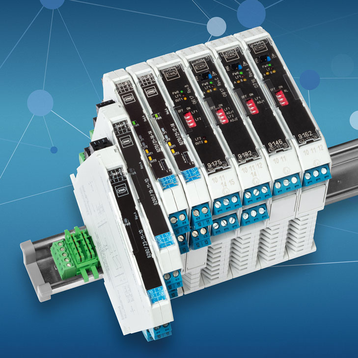
INTRINSIC SAFETY - THE INDISPENSABLE TYPE OF PROTECTION
The "intrinsic safety" type of protection covers a wide range of applications and is currently used in systems ranging from simple point-to-point wiring to digital automation for Industry 4.0. Ex i-protected solutions enable direct process data capture in hazardous areas, reduce installation work and can be tested and maintained during ongoing operation.
Development of intrinsically safe solutions
It has been a good 50 years since the first intrinsically safe field devices and associated safety barriers were used for the first time. This technology has changed over the years, but the typical signals, such as analogue 4–20 mA signals, are still in use today. The variety and versatility of applications has continued to grow. The Ex i (intrinsic safety) type of protection is now common.
For several decades, intrinsically safe fieldbus versions of Profibus DP and Modbus RTU have been primarily used to network remote I/O devices, operating terminals and analysis equipment. In addition, Ex i-protected fieldbus installations with PROFIBUS PA or Foundation Fieldbus H1 have proven to be useful for digital communication up to field devices. These developments didn't stop at wireless technology, either – in this sector, intrinsic safety allows more flexible use of antennae. Currently, the trend is heading towards intrinsically safe solutions for Industrial Ethernet. Corresponding standards for interoperable, intrinsically safe IP communication based on 10BASE-T1L and 100BASE-TX-IS technology are currently being developed and made ready for market in two working groups.
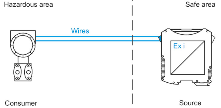
Simple handling during ongoing operation
The protective principle behind intrinsic safety is based on the concept of limiting the amount of energy in an electrical circuit to a non-ignitable extent, in order to ensure that sparks or thermal effects can no longer become sources of ignition. In this sense, this type of protection always comprises a combination of current/voltage sources, consumers and cables. This achieves very high levels of safety, allowing corresponding designs to be implemented even in extremely hazardous areas in Zone 0. Another advantage of the intrinsically safe type of protection is that it does not require the use of any special enclosure encapsulation, such as that required by Ex d and Ex p types of protection. However, the enclosures do need to meet the requirements of the surrounding environment, which are often met by the Ex e type of protection. As a rule, industrial-type cable bushings and plug connections are used for intrinsically safe circuits, which is particularly advantageous when using Ethernet or radio signals.
Ex i-protected devices are also extremely practical in terms of their handling during ongoing operation. Extensions and repairs can be performed on live equipment in hazardous areas (hot work) and devices can be added or separated without having to shut down the system or parts of the system entirely (hot swap). This is especially beneficial when troubleshooting problems or swapping out devices.
The basics of intrinsic safety
Intrinsically safe circuits are subject to the requirements of EN IEC 60079-11 and 60079-25 for device protection, as well as the structure and inspection of intrinsically safe electrical devices. The maximum permissible voltage and current values that ensure intrinsic safety are determined using ignition limit curves. For each explosion group, there is a corresponding curve. An electrical circuit is considered to be intrinsically safe if the pair of values made up of the voltage and current are underneath the ignition limit curve for the relevant explosive atmosphere. For use in Zone 1 or Zone 0, the permissible value is reduced by an additional safety factor of 1.5. For example, a piece of intrinsically safe electrical equipment with a power supply of 30 V intended for use in an explosive atmosphere in explosion group IIC must be supplied with a maximum of 102 mA in Zone 1.
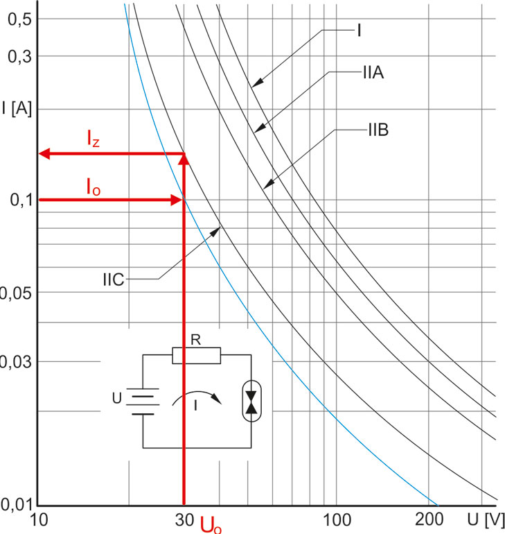
For use in Zone 0, a device with intrinsically safe circuits must comply with these current and voltage values even if two errors occur. For circuits in Zone 1, this applies if one error occurs. For use in Zone 2, it is sufficient for these values to be complied with during normal operation.
Depending on the intended application range (Zone 0, 1 or 2), the letter a, b or c is added to the Ex i designation. The same addition also indicates the Equipment Protection Level (EPL) for equipment approved for use in Zone 0, 1 or 2. The EPL, which is written as Ga, Gb or Gc, is indicated in the EC Type Examination Certificate and on the device's rating plate.

Selecting devices
As part of the project engineering process, devices are selected based on their zone classification and the expected characteristics of the explosive atmosphere (temperature class, explosion group). This step is not significantly different from the same procedure when using equipment that uses a different type of protection. However, it is unique in that when an electrical connection is to be established between an intrinsically safe field device and the automation system, as a general rule, a device that separates the intrinsically safe circuit from the "normal" electrical circuit is required. This means that the two devices need to be compatible.
Verification of intrinsic safety
Before commissioning an intrinsically safe circuit, the intrinsic safety of the circuit must be demonstrated according to DIN EN 60079-14 in order to ensure that the source, cables and consumers meet the requirements of the standard when interconnected. To obtain this verification, the values for the voltage, current and power of the circuit, as well as the capacitances and inductances of the energy storage device are evaluated. If the output values for the voltage source, current and power (Uo, Io, Po) do not exceed the input values of the connected consumer (Ui, Ii, Pi), and the connected capacitances and inductances of the consumers (Ci, Li) and cables (Cc, Lc) do not exceed the limiting values (Co, Lo), proof of intrinsic safety can be granted.
This verification must be documented. The values for the proof of intrinsic safety are taken from the operating instructions for the device in question. For the cable, either the values from the data sheet or exemplary values from the standard can be used. The definitive values for the cable are determined using the length.
It is somewhat more difficult to obtain proof of intrinsic safety for consumers with simultaneously effective inductances Li and capacitances Ci. Under these circumstances, users can either use values that have been certified for sources in this situation or they can halve the limiting values for Co and Lo in accordance with the "50% rule". Particularly complex individual cases – such as electrical circuits that are supplied from multiple sources – require detailed calculations, which R. STAHL is happy to perform on request as a service, as well as teaching users about intrinsic safety in specialist seminars.

Special case: Simple apparatus
When implementing the intrinsic safety protective concept, certain equipment that is considered to be "simple" can be used without requiring an EU-Type Examination Certificate. However, the use of this option demands caution, as it requires a thorough in-house assessment of these devices and equipment, such as switches, LEDs, thermocouples or Pt100 resistance thermometers according to IEC EN 60079-0 and 60079-11. Depending on the construction type, this involves evaluating factors such as heating behaviour, insulation to earth, IP protection, and more, as well as recording the results of these evaluations in writing. R. STAHL is happy to provide support to the sector during this process through standard-compliant evaluation and assessment of simple apparatus.
Intrinsically safe installation
The central installation requirements for intrinsically safe circuits set out in IEC EN 60079-14 include protection against the ingress of excess energy, for instance through the induction of switching voltages or other electromagnetic interconnections. Alongside correctly marking and routing cables and wires, users must ensure that separation distances are left between electrically conductive components in intrinsically safe and non-intrinsically safe circuits.
Inherently safe fibre optics
When transmitting digital signals over long distances, fibre optic cables are an alternative to copper conductors. Depending on the optical fibre that is used, fibre optic technology allows signals to be transmitted over distances of up to 30 km with very little interference. Multiple types of protection are available for use in hazardous areas. Inherently safe radiation (Ex op is) is very similar to intrinsic safety in terms of its key features. This type of protection involves limiting potentially ignitable optical energy to non-ignitable levels, even under fault conditions. The Ex-protected fibre optics can be connected and disconnected in hazardous areas without interrupting operation; this makes installation, modification and maintenance work simple and cost-effective.
Wireless in hazardous areas
For temporary installations, retrofitting existing networks and data exchange with mobile end devices, in particular, wireless communication represents an effective solution. R. STAHL creates application solutions based on a wide range of enclosure systems and components, with which conventional Wi-Fi access points and other network components can be adapted quickly for use in hazardous areas. Furthermore, R. STAHL's HFisolator from the 9730 series presents a solution that converts the radio signal into an intrinsically safe signal in order to operate devices with radio transmission using any industrially capable antenna – even in hazardous areas.
In short
Simple handling, high degrees of protection and versatile installation options make intrinsic safety an essential type of protection for process automation and data communication in hazardous areas. With Ex i-protected solutions ranging from individual isolators and I/O systems to bus networking and Ethernet communication, R. STAHL offers a wide range of products that covers the entire application spectrum. What's more, the explosion protection specialist also engineers and installs tailor-made solutions and supports system operators in producing standard-compliant proof of intrinsic safety.
